Information
Get binary: VERIGENSV.oRead howto: VERIGENSV.txt
Universal Memory Automata (UMA) provide a systematic way to implement near-memory compute hardware as proposed in [1]. The principle is based on the Finite State Machine (FSM) and Push Down Automata (PDA) theory. UMA theory extents this approach to an arbitrary number and configuration of memories and Verigen compiles synthesizable SystemVerilog code from UMA graphs. Designs are defined by control files that are derived from UMA state graph representations. The example packages in the table below provide a set of files to perform verification and coverage analysis with Verilator. A semi-custom design flow is proposed to implement real hardware.
The packages include configuration files for Verigen (.cfg), SystemVerilog code (.sv) derived from these configuration files and a Verilator simulation environment (.cpp) for functional and assertion based tests as well as coverage analysis. The executable is compiled with make and the Verilator simulation starts automatically. Use gtkwave to view the waveforms in logs/vlt_dump.vcd.
| Num | Description | Link |
|---|---|---|
| 1 | MESI cache coherency engine with key-lock | [.tgz] |
| 2 | Dual-Queue with alternating write and parallel two-port read | [.tgz] |
| 3 | Return Address Stack with concurrent read-write and key-lock | [.tgz] |
| 4 | Parametrized Content Addressable Memory with key-lock | [.tgz] |
| 5 | Parametrized 3-Level Table-Walk-Engine with TLB and key-lock | [.tgz] |
| 6 | Parametrized Opteron 1st-Level Cache with key-lock | [.tgz] |
While FSMs and PDAs are limited to state and stack memory, UMAs operate on user-defined memory configurations, configured as a Stack (LIFO), Queue (FIFO), RAM (Random Access), CAM (Content Addressable Memory) or combinations thereof. The number and of configuration of the storage is not limited in theory. All memory read and write operations are fully included into the state-transfer and output functions of the UMA.
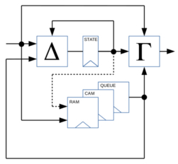
The structure of the UMA architecture is shown left. The attached memories need to support in-cycle read accesses to align with the corresponding state transfers while write accesses are executed with the state transfer, i.e. the write of the next state. Universal Memory Automata thereby perform transparent memory read and write accesses during state transfer and output generation so that the corresponding functions, i.e. state-transfer-functions and output-functions, can be extended as shown below. Multi-cycle memory accesses are supported by user-defined wait states.
The approach is flexible and becomes very powerful when using memory read or write accesses in combination with high-level arithmetic operators to define complex state transfers or output functions.
It is up to the implementer to secure an efficient implementation of the arithmetic circuits or let the synthesis tool do the optimizations. It appears most promising to use a semi-custom design flow and implement a near-memory computing architecture.
A transition between two states operates a source state (e.g. ID), a state transfer condition (including a series of memory read accesses per memory instance if desired) and a target state (e.g. RD). In case of N memory instances, the number of concurrent memory operations per cycle are less than or equal to N. The theory expects full-duplex (concurrent) read/write memory operations. So the number of concurrent memory operations per cycle is less or equal 2N, i.e. N read and N write operations on N individual memory instances.
The state transfer condition derives from the actual state, the input signals and the memory-read return data. If the state transfer condition is met, the automaton transfers to the target state and performs the memory write operations as defined by the state transfer. The number of read operations is limited to one read operation per read port per memory instance in a state transfer and the number of write operations is limited to one write operation per write port per memory instances while back-to-back read-writes are allowed and supported. States, state transfers and outputs are derived from a UMA graph.
Verigen is programmed in Perl to compile SystemVerilog code from UMA configurations files. Configuration files are text files that contain UMA definitions based on a simple structure as described below. The syntax supports a wide variety of constant and parameter definitions to keep definitions generic and simple.
The free version of Verigen comes with two examples, a MESI cache coherency protocol and a dual message queue with alternating write and parallel read capabilities. Examples provide all relevant files for SystemVerilog code gand testbench generation plus Makefiles and C++ files for fast simulation and coverage analysis with Verilator in a single package. More examples can be found in the table above.
A cache coherency protocol aims to secure data consistency in for example multi-CPU systems. Here, a MESI cache coherency protocol is implemented with a Universal Memory Automata.
A Universal Memory Automata (UMA) representation (left figure) is defined by a configuration file and the VERIGEN tool compiles synthesizable HDL code at Register Transfer Level.
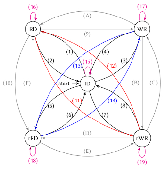
In UMA finite state graph representation of the MESI cache coherency protocol, states are named (RD) for read access, (WR) for write access, (rRD) for remote read access and (rWR) for remote write access of a CPU. The graph performs state transfers according to the input signals 'cpu', 'rd' and 'wr' as well as the memory address 'addr', where 'cpu' indicates if the memory access is remote or not. Remote in this context means a far CPU to execute a 'rd' or 'wr' operation on 'addr' to the cache memory where data consistency is secured for.
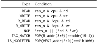
In order to simplify the design effort and make the code morCe maintainable, recurring logic conditions are recommended to be defined as static expressions as shown in the right figure to be then used in the state transfer logic and for memory operations. Thereby, complex conditions are easy to maintain and synthesis tools are supposed to not duplicate logic.
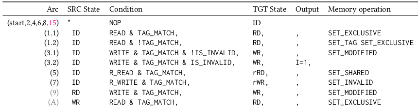
As exemplary shown above, compare operations on memory return data are easily performed on virtual POP() operations. The expressions are used to create state transfer conditions as shown in the figure below. There, some state transfers and memory operations are defined for the state transitions in the finite state graph shown above.
The state graph is translated into a configuration file and Verigen compiles SystemVerilog code from the configuration file from an invocation 'VERIGEN_FREE -f mesi.cfg' to create a file MESI.sv and a simple testbench MESI_tb.sv.
Configuration files are processed by Verigen to compile SystemVerilog code. They are easy to maintain and follow a simple structure.
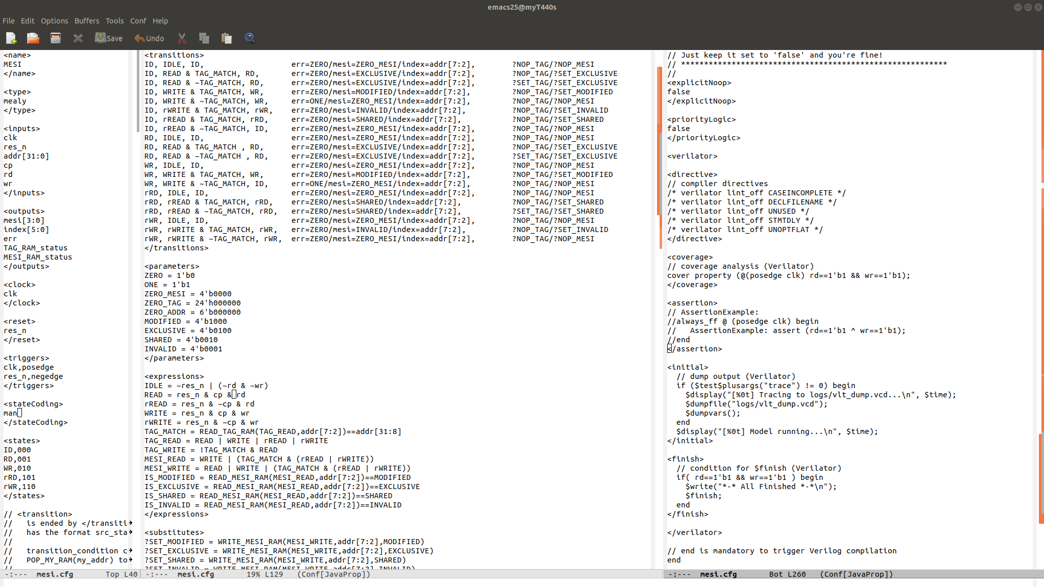
The module name is defined by the tag 'name'. In the example, the module is named 'MESI'.
The type of the automaton is defined by the tag 'type'. In the example, the automaton is of type 'mealy'. Users can also choose 'moore' or 'simple moore'.
Inputs are defined by the tag 'inputs'. In the example, the automaton has the inputs 'clk', 'res_n', 'addr[31:0]', 'cp', 'rd' and 'wr'.
Outputs are defined by the tag 'outputs'. In the example, the automaton has the outputs 'mesi[3:0]' and 'index[5:0]'.
States are defined by the tag 'states'. In the example, the automaton has the states 'ID', 'RD', 'WR', 'rRD' and 'rWR'. In case of manual state encoding, codes are entered after the state name, separated by a comma.
State transfers are defined by the tag 'transition'. In the example, the automaton has 13 exemplary state transitions. State transitions are organized as follows: source state, state transfer expression, target state, output settings, memory action. State transfer expression might contain boolean expressions on inputs and memory return data and status.
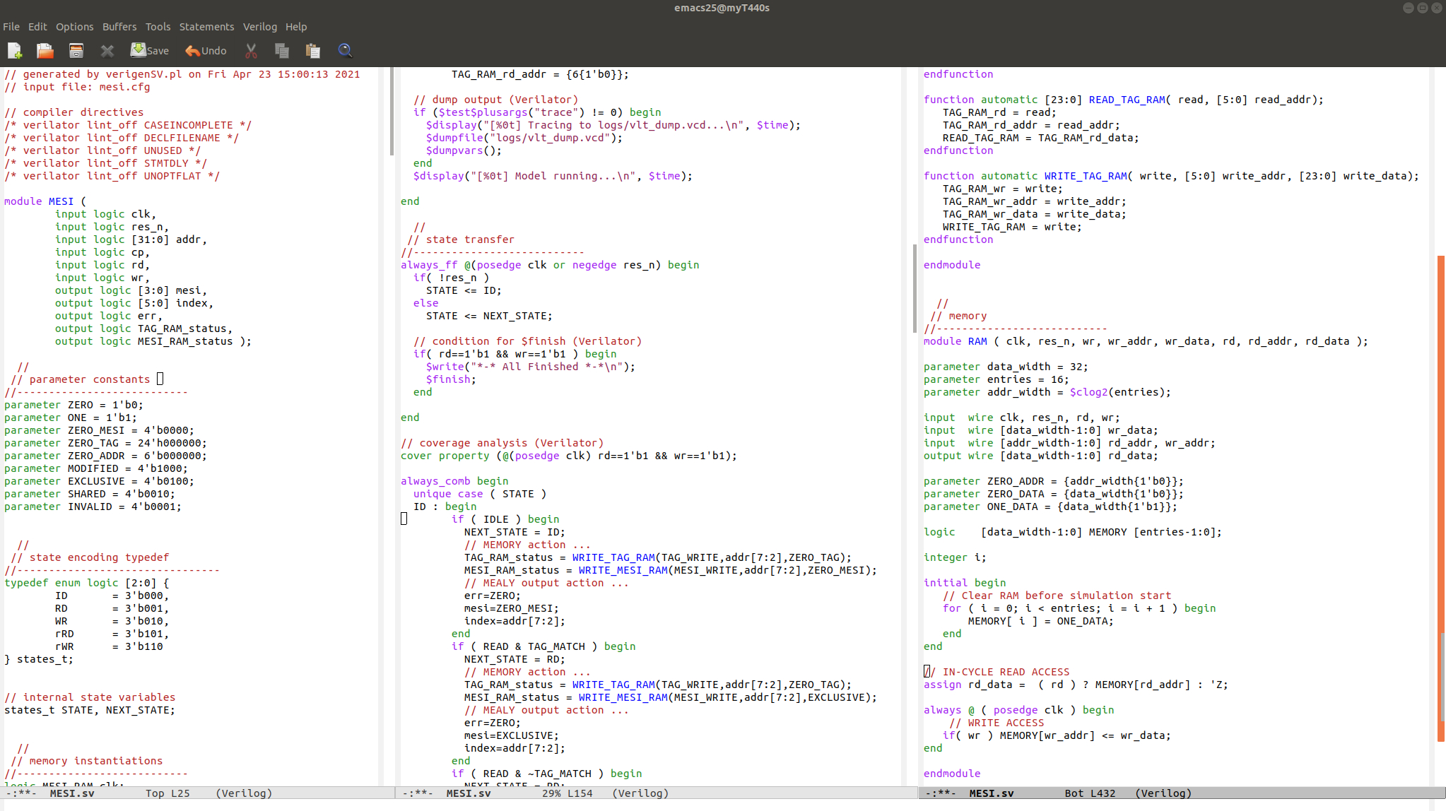
The figure shows the SystemVerilog code compiled by Verigen for the MESI cache coherency hardware. Data is stored into a RAM called MESI with a WRITE_MESI_RAM() operation and retrieved with a READ_MESI_RAM() operation. Two memories TAG ram and MESI ram are instantiated and cache lines change their status due to read/write situations of CPUs for memory accesses on input 'addr[31:0]'.
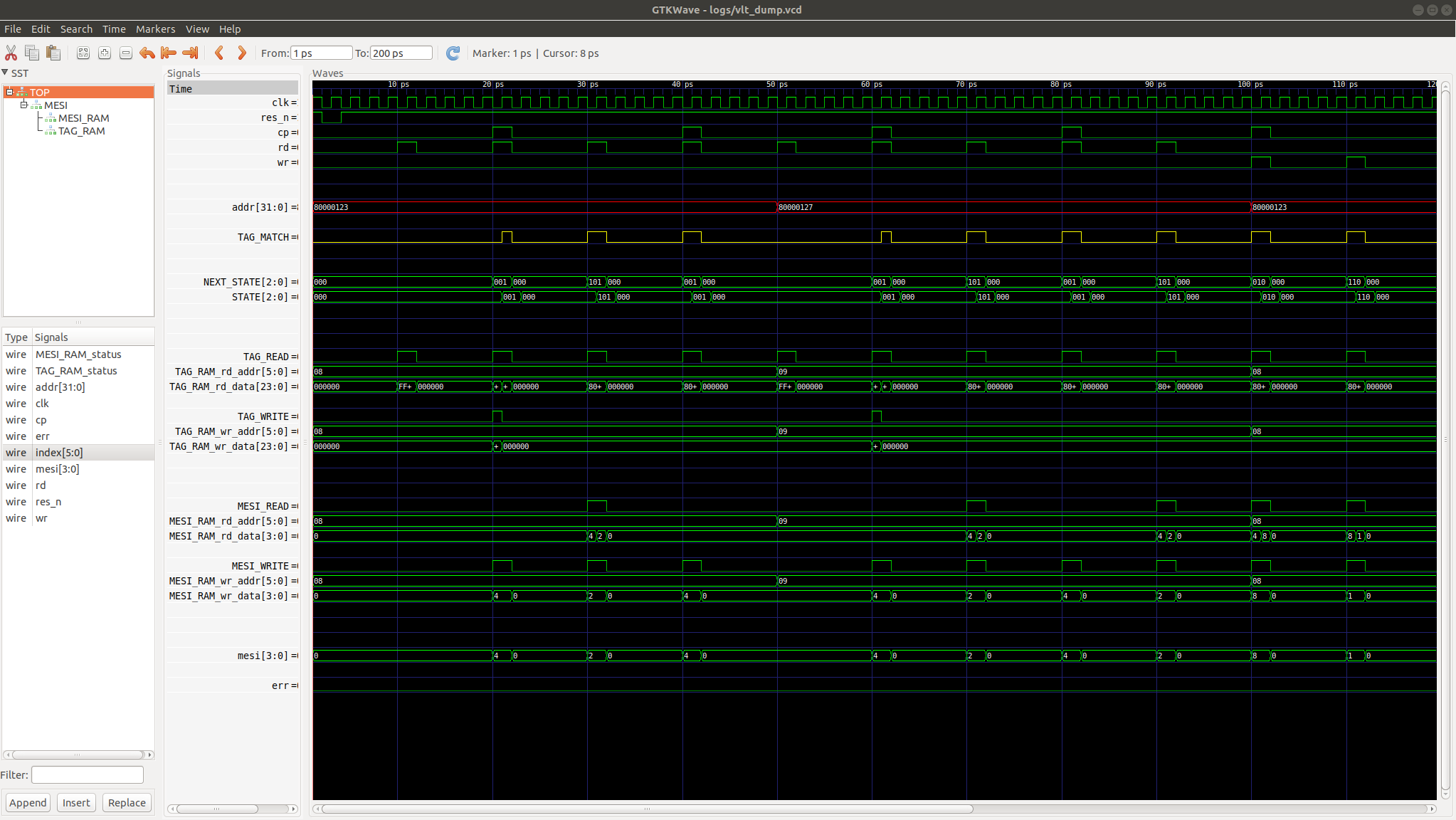
Verigen provides further useful functions for clock and reset definitions, trigger edge configurations and more. The example provides all files to perform a Verilator simulation and generate trace files for the following signal diagram.
A trial version of Verigen is available to process five states and two memories of type RAM, QUEUE or STACK. Get the binary executable here and see the examples in the table above to learn how to use Verigen. The code is compiled on Ubuntu 18.04.5 LTS. A Windows version is available upon request.
[1] M. Fertig, "Universal Memory Automaton and automated Verilog HDL code generation for a cache coherency snooping protocol", Proceedings of the 63th Workshop of the Multi-Project-Group, Mannheim, February 21st, 2020. [PDF]